The power loss of switching devices is an important part of the evaluation of switching devices, and is also an advanced analysis function for many oscilloscopes. In fact, although many laboratories are equipped with a power loss measurement environment, they also put a lot of money on equipment and probes. However, if time shifts are ignored, all test results will lose meaning.
1.1 What should be considered in the measurement of switching losses?
In the actual measurement evaluation, we use one channel to measure the voltage, and the other channel to measure the current. Then the software obtains the power curve by multiplying, and then the final result is obtained by integrating the time interval.
Here are two points to note:
Ensure that the bandwidth of the oscilloscope and probe is sufficient, and accurately acquire the waveform of the switching device during turn-on and turn-off;
Accurately measure the phase and ensure the correspondence between voltage and current.
The bandwidth is better understood, but how can we guarantee the voltage and current correspondence?
1.2 Effect of Time Offset on Measurement Results
When there is a time offset between the voltage channel and the current channel, the measurement result is significantly higher or lower, and the faster the switching speed of the device, the more significant the effect of the offset. Figure 1 shows the MOS transistor's turn-off loss measurement principle. It can be seen that the correct measurement result can only be obtained after correction. It is worth noting that this offset is ubiquitous due to the difference between the implementation principle of the voltage probe and the current probe and the transmission cable length of the probe.
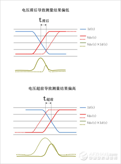
Fig. 1 Effect of offset between channels on measurement results
1.3 How to correct the channel offset?
As shown in FIG. 2, the offset correction jig can directly correct the time offset between the voltage probe and the current probe. The basic principle is that the fixture generates a set of voltage and current pulse signals with zero phase difference and acts on the voltage and current probes at the same time. Observe the time offset of the pulse signal after passing through the probe through the oscilloscope and correct the offset time on the oscilloscope.
The fixture is powered through a USB interface and is easy to use. The time offset can be corrected manually or automatically. Using offset correction jigs, the waveforms before and after correction are shown in Figure 3 and Figure 4, respectively.
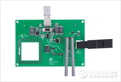
Figure 2 ZDF1000 offset correction fixture
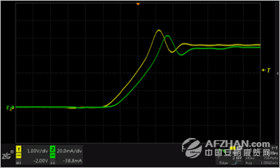
Figure 3 Waveform before offset correction
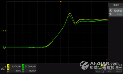
Figure 4 Offset corrected waveform
1.4 The Effect of Extension Lines on Transmission Delay
In addition to performing offset correction, in the actual measurement, attention should also be paid to the influence of the extension line. A typical test diagram is shown in Figure 5. Because the current clamp can not measure the current directly on the PCB, the current must be drawn through the extension line. The extension line will introduce the transmission delay. The ordinary copper extension line can be calculated by 33.5ps/cm, and the oscilloscope delay correction parameters Make compensation. Similarly, the extension of the voltage probe will also bring about the transmission delay, which can be compensated by adjusting the delay correction parameter according to the advance lag relationship in the actual measurement. Taking FIG. 5 as an example, assuming that the length of the extension line is 100 cm, the delay time of the current channel is: 33.5 ps/cm×100 cm=3.35 ns. After using the offset correction jig to complete the correction, the current channel's delay correction time should be adjusted so that it is 3.35 ns ahead of the voltage channel.
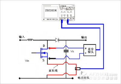
Figure 5 Typical test schematic
Through the above analysis we can see that: when using an oscilloscope to measure the switching loss of high-speed switching devices, in addition to ensuring that the waveform measurement of the voltage channel and the current channel is accurate, it is also necessary to pay attention to the time offset between channels, which is introduced by the probe. The time offset, which introduces a large error for the measurement itself. Therefore, when accurately assessing the power loss, it is necessary to correct the channel delay using an offset correction jig.
Sequin Embroidery,Embroidery Sequin Fabric,Popular Wedding Fabric,Sequin Lace Fabric
Shaoxing MingFang Textile Co., Ltd , https://www.printings-fabric.com