Depletion rate and loss rate are two important technical and economic indicators that reflect the level of mine production management. They are the key link for mines to reduce costs, increase efficiency, and optimize management [1]. In recent years, a large number of scholars have carried out detailed research on measures to reduce the rate of depletion and loss, and have achieved certain results [2-3]. In this study yuanjiacun iron ore steep metamorphic sedimentary ore for the study, the characteristics of different segments of the block blasting, blasting and dilution analysis, loss of association, application software and the simulation precision blasting detonator based, The analysis establishes a wide adaptability and wear-through technology for steeply inclined and medium-thickness sedimentary metamorphic iron ore.
1 Project Overview
Yuanjiacun Iron Mine is located in Jixian County, Shanxi Province. The production capacity of ore is 22 million t/a and the rock is 63.8 million t/a. The mining area is located in the uplift of the Shanxi fault block in the central part of the North China block. It is a typical typical sedimentary metamorphic deposit in the early Cambrian metamorphic geological body of the Luliang Mountain [4]. There are 3 ore belts and 15 ore bodies, which are mostly layered and lenticular. They are in integrated contact with the surrounding rock and have a stable tendency along the inclination angle of 70°~80° and inclined to the direction of S75°~80°E. However, due to the intercalation of the diabase , the original layered and lens-shaped ore bodies are further bifurcated and dismembered, which makes the ore body shape more complicated. The ore body has large thickness and concentrated reserves. The total proven reserves in the zone are 1.26 billion tons, and the largest in the 10#, 1#, and 11# ore bodies, accounting for 59.5% and 18.1% of the total reserves, respectively. 10.5%. The ore body is exposed on the mountain girders and has good open-pit mining conditions. Therefore, using topographic conditions, using top-down, north-south horizontal and horizontal horizontal stratified mining methods, it is beneficial to realize micro-fine The comprehensive utilization of multi-grade ore of granule complex and difficult to choose red magnetic mixed iron ore. The ore uses the automobile-semi-mobile crushing-tape to develop the transportation system. At the beginning, a single vehicle is used to develop the transportation system. Later, a set of automobile-semi-mobile crushing-tape system [5-6] is arranged in the upper and lower plates.
For the steeply inclined open-pit mines with longitudinal mining, the key part of depletion and loss is the boundary of mineral rock. Generally, the sub-explosion and depletion mining are used to improve the depletion and loss indicators. From the upper plate to the lower plate, the exploitation can be fully utilized after blasting. Step slope angle, therefore, when placing the blasthole near the boundary of the rock mass, the bottom of the blasthole should be placed at the boundary of the rock, and the back of the blasthole should be strictly controlled, so that the looseness of the blasting is as close as possible to the boundary of the rock. Under the collapse, the separation of ore is achieved. In the horizontal mining of the steep slope ore body of Yuanjiacun Iron Mine, in the early stage, the understanding of the boundary line of the ore-rock geological body is insufficient. In the perforation blasting, the edge of the blasting block is often rock or ore, which causes the poverty. And loss. For the interbedded rock interbed between no more than 50m, it can theoretically be divided into sub-explosive mining, but the perforation, shovel loading efficiency is low, the process management is difficult, and the high-frequency sub-wearing breaks down the single blasting block. The amount of depletion loss is difficult to significantly improve the depletion and loss of ore as a whole.
2 complete wear and explosion key technology
2.1 Classification of blasting blocks
In this study, the face of the blasting block and the geological plan are divided according to the inclination angle of the ore body 70°~80°. The interlayer of the rock (mine) in the ore (rock) body is based on the principle of stability of the ore (rock) and ore body. The division is basically covered by the occurrence pattern of Yuanjiacun iron ore (rock). The results are shown in Table 1.
Table 1 Classification of blasting block segments 
2.2 Reasonable cloth hole
Firstly, the sketch of the face of the blasting block is drawn, and the 3D geological body model of the mine is used to determine the range of the blasting block. Then, according to the boundary of the blasting block, the location of the hole is determined to avoid the blasthole located at the boundary of the ore. on.
2.3 strict control of perforation
The perforation operation is carried out strictly according to the designed hole position, and the characteristics of the slag returning in the perforation are recorded. Finally, the longitudinal section of each hole spacing of the blasting block is drawn, and the three-dimensional geological model of the ore body is corrected and corrected, which serves as the basis for determining the blasting design.
2.4 blasting design
The blasting method is based on the original blasting parameters and is based on the fine blasting operation of the geological body shape and parameters of each ore in the blasting block. The key to the control of blast depletion loss is that there is a clear distinction between the direction and displacement of blasting throwing in non-homogeneous geological bodies. It is reflected in the design of blasting network that the delay time of the blastholes on both sides of the rock boundary should be equal or close. The isochronal line should be "V" shaped and the inflection point should be on the ore boundary.
3 example analysis
3.1 Overview of the blasting block
1710-1695-294# The blasting block section is located in the thick 10# mine body, which belongs to the B2 type in Table 1. It is better to adopt the whole wear-and-break method, using the roller drill operation, the hole diameter is 310mm, and the hole net parameter is 6m×8m. 1). In Fig. 1, the shaded part is the ore body, and the colorless part is the rock mass.

3.2 detonation network design
The detonation time between the holes and the rows of the surface detonator is 3~8ms/m and 9~15ms/m, respectively. The Oricai Exel series is 25, 65 and the hole is 400ms. The Aussie shotplus5 software was used to design the detonation network (Figure 2). It can be seen from Fig. 2 that the detonation network is composed of three sub-networks, the 11#, 19#, and 1# holes are detonation points, and the 25ms detonation delay at the 11# hole ensures that the delays of adjacent head row holes of each sub-network are consistent. However, the delay difference of adjacent holes in the second row is 25ms, the third row is 50ms, and the nth row is 25(n-1)ms. When the number of rows is small, the delay time of the blastholes on both sides of the rock boundary can be met. The inter-row delay of the two sub-networks in Figure 2 is modified to 90ms, which is limited by the inherent delay of the segment, and can be equivalent to the delay of 25ms and 65ms2, so that the delay of adjacent holes of each sub-network is consistent.

The blasting simulation is carried out on the optimized network design. The isochronal and blast displacement directions are shown in Figure 3 and Figure 4, respectively. It can be seen from Fig. 3 and Fig. 4 that the isochronal line is evenly distributed and has a "V" shape, and an inflection point appears on the boundary of the rock, and the direction of the blasting displacement of each network is consistent with the design.


3.3 blasting effect
The blasting effect is shown in Figure 5. It can be seen from Fig. 5 that the separation effect of the ore after blasting is obvious and the effect is remarkable.

4 discussion
(1) The angle between the rock boundary and the free surface reflects the mining conditions and is the basis for selecting the blasting scheme. If the angle is less than 90°, the sub-expansion is restricted, and it is better to use the whole wear and detonation;
(2) The increase of the number of blasting rows does not change the delay equivalence of adjacent holes in the subnet. In theory, the number of blasting rows can be unrestricted. In fact, as the number of rows increases, the space in the rear row is insufficient and the displacement is too small. The formation of extrusion and back-turning, the separation of the ditch of the ore boundary tends to weaken, weakening the throwing separation of the design, and at the same time, with the increase of the number of rows, the height of the blasting block is obvious, which is not conducive to the subsequent shovel loading operation. Depletion, loss control, after field test, the limit number of rows is 8 rows, with 6 rows as the best.
(3) The digital electronic detonator replaces the traditional chemical agent delay body with an electronic delay body, which can effectively solve the technical problems of unstable delay precision and poor precision of the chemical delay body. Based on the principle that the blasthole delays on both sides of the ore boundary are equal or close, the digital electronic detonator rock can directly create the optimal network delay, and the separation effect is better.
(4) The whole wear-through detonation is a design of the hole, perforation and blasting on the basis of a certain degree of research on the ore-rock geological body in the stripping zone. With the construction of the 3D geological model of the Yuanjiacun iron deposit, Combined with the modification of the ore-rock conditions in the perforation process, the ore-rock geological body model in the blasting block section will be accurately constructed. For the determination of the blasting block section and the ore-rock geological structure, ore quality, ore body geological boundary and ore body interlayer in the blasting block section. The control is positive.
(5) The effect of the wear-through and detonation technology is obviously effective in improving the depletion and loss index of the steeply inclined and medium-thickness sedimentary metamorphic open-pit mining. Since the Yuanjiacun iron mine has been in the second half of 2014, the loss rate is flat. The depletion index fell from 4.07% in the first half of the year to 3.45% in the second half of the year. From January to August 2015, the loss rate dropped from 3.80% in 2014 to 3.40%. The conversion rate dropped from 3.76% for the full year of 2014 to 3.62%.
(6) The whole wear-through detonation technology is the choice under the condition of high productivity and low depletion loss. If the mining conditions permit, the sub-explosive mining should be preferentially divided.
references
[1] Zhao Shuangping, Wang Aimin. Discussion on improving statistical methods of open pit mine production [J]. Metal mines, 1993 (11): 17-19.
[2] Chen Lin. Quality management and control in the production process of dolomite ore [J]. Baotou Steel Technology, 2010, 26 (3): 16-18.
[3] Shi Liansong, Tang Zhixin, Yan Zhongyi, et al. Study on Blasting Method in Mining and Stripping Process of Hami Red Rock Meiling Open-pit Mine[C]∥Review and Prospects of China's Mining Technology for Ten Years. Beijing: Metallurgical Industry Press, 2012: 392-394.
[4] He Hong. Discussion on the formation conditions of the deposit metamorphic iron deposit in Yuanjiacun, Song County, Shanxi Province [J]. North China Land Resources, 2013, 54 (3): 89-94.
[5] Liu Hongwei. Analysis of Yuanjiacun Iron Mine Development System Design [J]. Mining Engineering, 2011 (6): 16-17.
[6] Pan Tao, Chen Huijun, Zhao Mingsheng, et al. Research on the influencing factors and improvement measures of digital electronic detonator accuracy error [J]. Blasting, 2014, 31(2): 135-138.
Author: Bai Jun, Wang Y F.; Taiyuan Iron and Steel Group Mining Co., Ltd. Lan County;
Article source: "Modern Mining"; 2016.8;
Copyright:
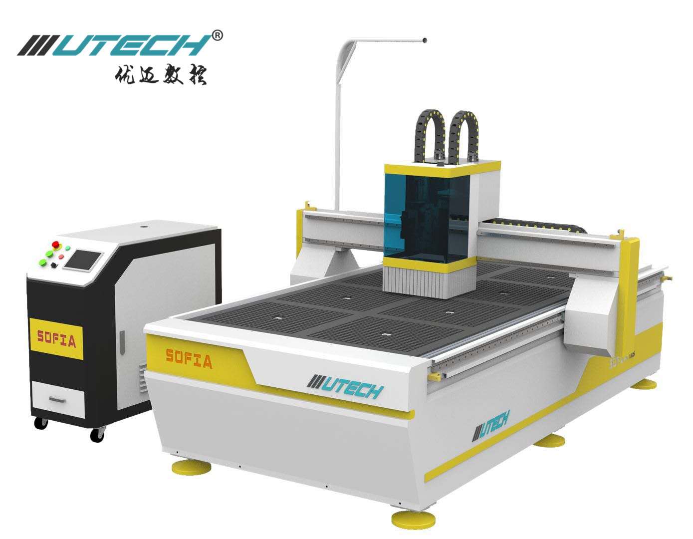
CNC Oscillating Knife Cutting Machine
Concepts:
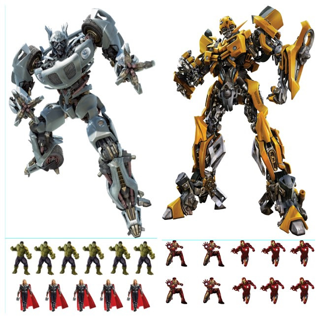
Oscillating Knife: Oscillating Knife cutting has the advantages of small cutting force, low cutting heat, high surface quality of the workpiece, easy chip handling, improved tool durability, stable processing and high production efficiency.CNC VISION SYSTEM: CCD Vision Cutting system contains two operating modes: direct cutting mode and photo processing mode. Therefore, the processing route manufacturing steps
Differentiate: Direct cutting does not need to draw a photo point, and the tool path file for drawing a photo point can be processed through the buttons on the interface.
INDUSTRIES:
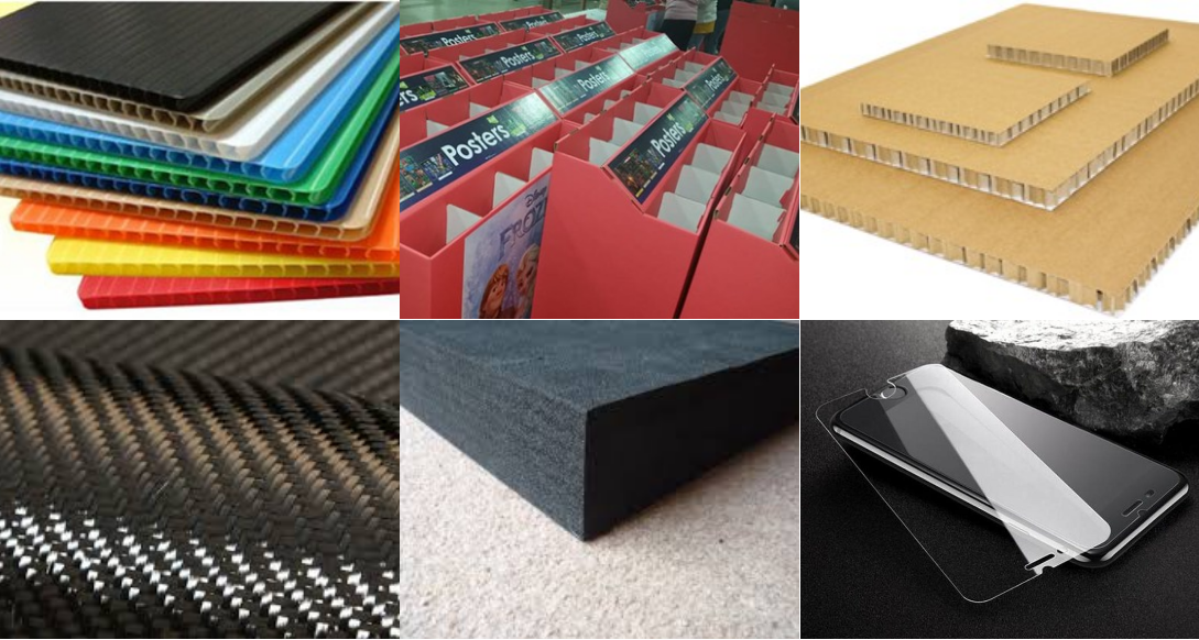
Sign and Graphics, Digital Printing, Packaging, Automotive, Recreational boat, Exhibits, and Fixtures, Sign Making, Gasket Materials, Arts and Crafts, etc.
Carpet, Felt, Foam, Closed Cell Foam, Fiberglass Insulation, Composites, Gasket Materials, Rubber, Fabric, Honeycomb Cardboard, Single-ply Cloth/Fabric, Corrugated Cardboard/Paperboard, Vinyl Veneers, Snowboard, Corrugated Plastic, Leather Goods, wood veneer for inlay/marquetry artwork, Carbon fiber pre-preg laminates for aerospace, military, and automotive components i.e.
Why choose Oscillating Knife Cutting Machine
-
Advanced Weihong 53C+TROCEN control system, easy and precise operation;
- The heavy duty thickened bed is welded by square pipe, side hanging
- structure, heavy column, 150*200mm gantry;
- Patent type 1:8 reducer;
- Has the advantages of small cutting force, low cutting heat, high surface quality of the workpiece, easy chip handling, improved tool durability, stable processing and high production efficiency.
- The high precision CNC Oscillating Knife Cutter can induce draft separately and easily cut small pieces.
Main features:
- Working area: Could be customized(1300*2500mm; 1500*3000mm; 2000*3000mm etc.);
- Voltage: 220-420v, 3phase, 50-60hz;
- Spindle:3.5kw air cooling spindle and Oscillating knife+CCD camera;
- X Axis & Y Axis System: Germany ASK/PMT/GC-HIWIN 20 linear guide+Flange slider+Precision 1.25module helical rack+Patent type reducer structure 1:8
- Table: Vacuum & T-slot table;
- Precision machined aluminum parts, using aviation aluminum T6061/6063 material, CNC processing center precision manufacturing.


Oscillating Knife Cutter with CCD
Oscillating Knife Cutter With Ccd,Oscillating Knife Cutter,Cnc Router With Oscillating Knife,Oscillating Knife Atc Contour Cutter
Shandong U-May CNC Technology Co., Ltd. , https://www.sesamecnc.com